Mtd 242A645-000 User Manual
Browse online or download User Manual for Tools Mtd 242A645-000. MTD 242A645-000 User Manual
- Page / 12
- Table of contents
- BOOKMARKS
Rated. / 5. Based on customer reviews
$1.00
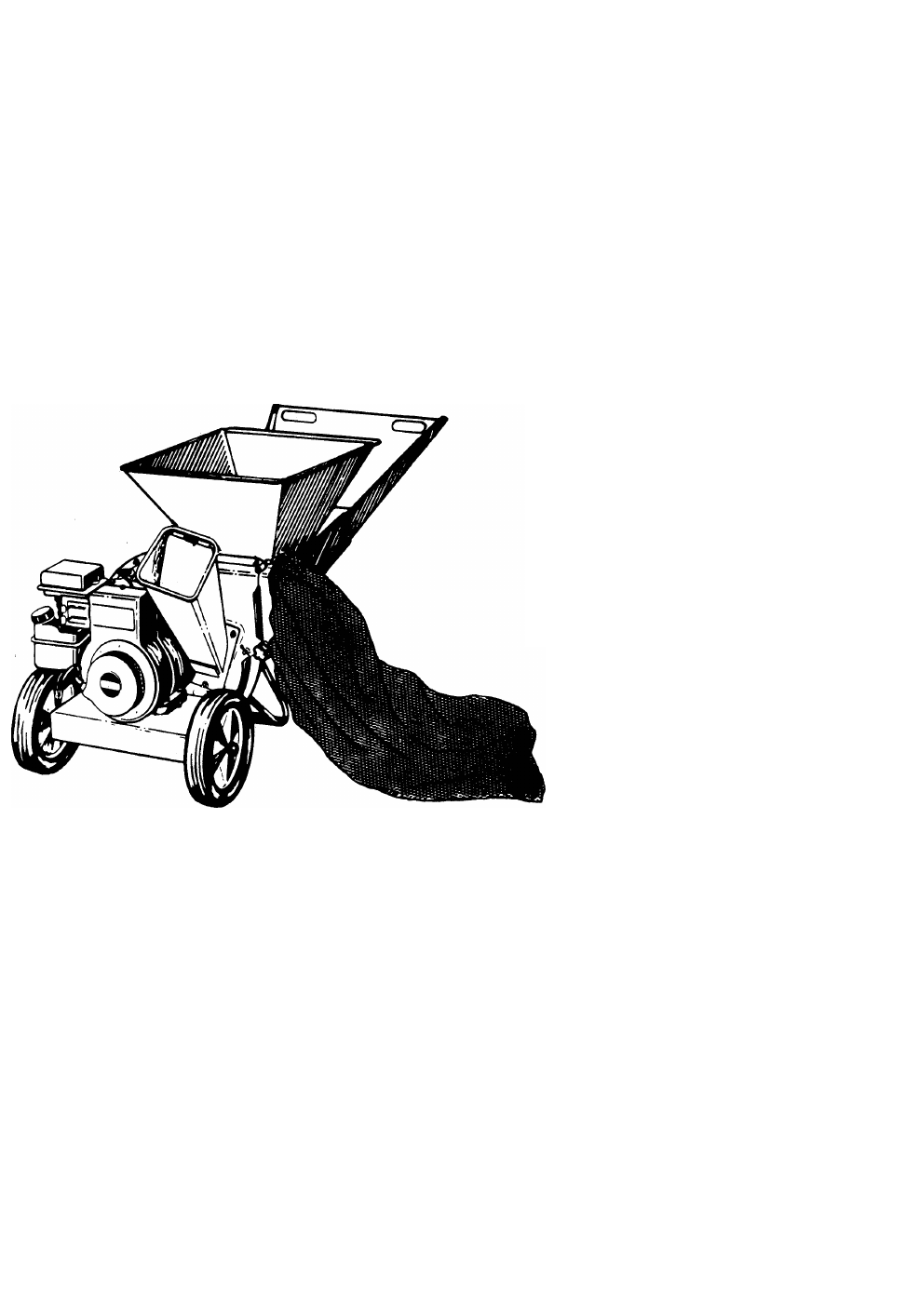
OWNEirS GUIDE
• ASSEMBLY • OPERATION • MAINTENANCE • PARTS •
5 and 8 H.P.
SHREDDERS
Model Numbers
242-645-000
242-648-000 /
rs MULiJ
242A645-000
242A648-000j
’XMPELLEP^
/Iss/
Important:
Read Safety Rules
and Instructions Carefully
IMPORTANT!
Record the Model No. and Mfg. Code which
appear on your unit in the space below. You
must have these numbers, along with the date
of purchase, in order to receive warranty or ser
vice.
MEETS ANSI SAFETY STANDARDS
MODEL NO. MFG. CODE
AMERICA
WARNING: This unit is equipped with an internal combustion engine and should not be used
on or near any unimproved forest-covered, brush-covered or grass-covered land unless the
engine’s exhaust system is equipped with a spark arrester meeting applicable local or state
laws (if any). If a spark arrester is used, it should be maintained in effective working order by
the operator.
In the State of California the above is required by law (Section 4442 of the California Public
Resources Code). Other states may have similar laws. Federal laws apply on federal lands.
A spark arrester for the muffler is available through your nearest engine authorized service
dealer or contact the service department, P.O. Box 360900, Cleveland, Ohio 44136.
FORM NO. 770-7048G
Summary of Contents
Page 1 - OWNEirS GUIDE
$1.00OWNEirS GUIDE• ASSEMBLY • OPERATION • MAINTENANCE • PARTS •5 and 8 H.P. SHREDDERSModel Numbers 242-645-000 242-648-000 /rs MULiJ242A645-000 242A
Page 2 - SAFETY RULES
Models 645 and 6^ 8 NOTEThis instruction manual covers various models, and all specifications shown do not necessarily apply to your model.
Page 3 - ASSEMBLY INSTRUCTIONS
Models 645 and 648PARTS LIST FOR MODELS 645 and 648 SHREDDERSEF.^O.PARTNO.CODEDESCRIPTIONREF.NO.PARTNO.CODEDESCRIPTION1742-0571 N37710-0157Hex Bolt 5/
Page 4
TROUBLE SHOOTINGPROBLEMPOSSIBLE CAUSE! 5)CORRECTIVE ACTIONEngine fails to start 1. Fuel tank empty, Dr stale fuel.2. Spark plug wire d sconnected.3.
Page 5 - OPERATION
SAFETY RULESAWARNING: TO REDUCE THE POTENTIAL FOR ANY INJURY, COMPLY WITH THE FOLLOWING SAFETY INSTRUCTIONS. FAILUF E TO COMPLY WITH THE INSTRUCTIONS
Page 6 - TO START ENGINE
ASSEMBLY INSTRUCTIONScnnATTACHING THE LOWER [A LEAF RAMP SECTIONHex Bolt-5/16-18 X 8-3/8" LongWasher f ( } )5/16" I.D.Hex Lock Nut 5/16-
Page 7 - MAINTENANCE
Spacers (Inside Hinae^Chute C efiectorAFIGURE 2.WARNING: Make certain the spark piug wire is disconnected and moved away from the spark p
Page 8 - REMOVING THE FLAIL SCREEN
ATTACHING THE CATCHER BAGYour shredder is equipped with a catcher bag to catch the shredded material.To attach the bag, place the opening of the bag o
Page 9 - CARBURETOR ADJUSTMENT
BEFORE STARTING1. Place the shredder on a firm, level surface2. Service engine with gasoline and oil as inj tructed in the separate engine manual pa
Page 10 - Models 645 and 6^ 8 NOTE
*“*K,ta?-.FIGURE 10.No Larger Than 1/2" DiameterFIGURE 11.To lower the leaf ramp, use one hand to grasp the handle at the top of the lea
Page 11 - Models 645 and 648
mended at the start of each season; check engine manual for correct plug type and gap specificat ons.Clean the engine regularly with a clot
Page 12 - TROUBLE SHOOTING
NOTE: When reassembling, make certain the opening on the back-up plate is toward the bottom of the unit. The back-up plate may be reversed to provide
Related products and manuals for Tools Mtd 242A645-000
Tools Mtd 248-650-000 User Manual
 (16 pages)
(16 pages)
Tools Mtd 245-650-000 User Manual
(12 pages)
(12 pages)
Tools Mtd 24635A User Manual
(14 pages)
(14 pages)
Tools Mtd 249-645A User Manual
(20 pages)
(20 pages)
Tools Mtd 242-630-000 User Manual
(16 pages)
(16 pages)
Tools Mtd 243-650 User Manual
(8 pages)
(8 pages)
Tools Mtd 246-315D000 User Manual
(8 pages)
(8 pages)
Tools Mtd 630 thru 635 User Manual
(16 pages)
(16 pages)
Tools Mtd 24596-8 User Manual
(12 pages)
(12 pages)
Tools Mtd 242-654 User Manual
(6 pages)
(6 pages)
Tools Mtd 24632S User Manual
(12 pages)
(12 pages)
Tools Mtd 645B thru 651B User Manual
(12 pages)
(12 pages)
Tools Mtd 241-645A User Manual
(16 pages)
(16 pages)
Tools Mtd 243-635-000 User Manual
(20 pages)
(20 pages)
Tools Mtd 246-632-000 User Manual
(10 pages)
(10 pages)
Tools Mtd 243-638-000 User Manual
(20 pages)
(20 pages)
Tools Mtd 244-648D401 User Manual
(12 pages)
(12 pages)
Tools Mtd 24642-A User Manual
(12 pages)
(12 pages)
Tools Mtd 245-596-000 User Manual
(12 pages)
(12 pages)
Tools Mtd 242-632-000 User Manual
(20 pages)
(20 pages)
© 2020, manymanuals.com. All rights reserved. | 7.757 s |
 Manymanuals.com
 Manymanuals.de
 Manymanuals.fr
 Manymanuals.it
 Manymanuals.pl
 Manymanuals.cz
 Manymanuals.es
 Manymanuals-pt.com
Comments to this Manuals