Mtd 454 User Manual
Browse online or download User Manual for Gardening equipment Mtd 454. MTD 454 User Manual
- Page / 20
- Table of contents
- BOOKMARKS
- OPERATOR’S MANUAL 1
- TABLE OF CONTENTS 2
- FINDING MODEL NUMBER 2
- ENGINE INFORMATION 2
- CONTACTING CUSTOMER SUPPORT 2
- Training 3
- Preparation 3
- Operation 3
- Maintenance & Storage 4
- Your Responsibility 4
- WARNING: 5
- Attaching Control Rod 6
- Final Clutch Adjustment 6
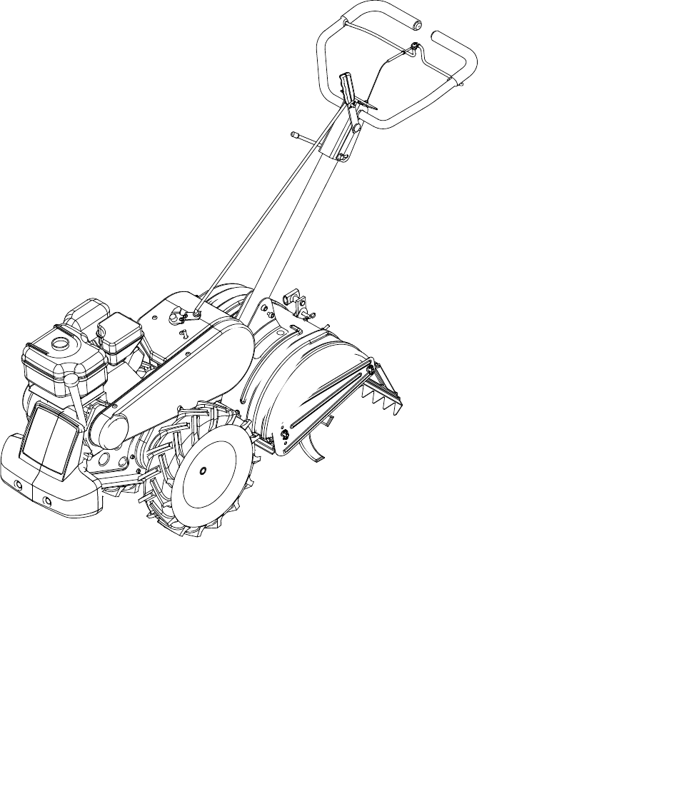
- SECTION 3: KNOW YOUR TILLER 7
- To Stop Engine 9
- Setting The Depth 9
- Operating the Tiller 9
- Handle Adjustment 10
- Belt Tension Adjustment 10
- Engine Adjustment 10
- Lubrication 10
- Cleaning Tine Area 11
- Belt Replacement 11
- Off-Season Storage 11
- Model 454 14
- IMPORTANT: 20
Summary of Contents
Rear Tine TillerModel 454OPERATOR’S MANUALIMPORTANT: READ SAFETY RULES AND INSTRUCTIONS CAREFULLYMTD LLC P.O. BOX 361131 CLEVELAND, OHIO 44136-0019War
10SECTION 5: MAKING ADJUSTMENTSWARNING: Never attempt to make anyadjustments while the engine is running,except where specified in operator’smanual.H
11Wheel ShaftsRemove wheel assemblies and lubricate the axle shafts at least once a season.Cleaning Tine AreaClean the underside of the tine shield af
12SECTION 7: TROUBLE SHOOTING GUIDENOTE: For repairs beyond the minor adjustments above, contact your local authorized service dealer.Trouble Possibl
13Notes
14Model 454 52132935165335164631281245171744366333152753643420402113418104223722368473237502510924365134452641363516291949443314351621428351614114814
15Model 454Ref. No.Part No. Part Description1. 611-0020 Wheel Shaft Ass’y 33T2. 611-0021 Tine Shaft Ass’y: 18T3. 611-0128 Jack Shaft Ass’y4. 611-0129
16Model 4542018823101606137622534276430396326323633312966264130302428354026494450595165535556545758444642491116631471951726061121512382122677070686927
17Model 454Ref. No.Part No. Part Description1. 747-1152 Shift Rod2. 649-0041 Upper Handle Ass’y 3. 649-0034 Lower Handle Ass’y4. 710-3005 Hex Screw 3/
18Model 454181724192745441226961825142820211422231652171315340434241393233313029363437383510
19Model 454Ref. No.Part No. Part Description1. 686-0111 Belt Cover Bracket Ass’y2. 710-0237 Hex Bolt 5/16-24 x .62”3. 710-0412 Hex Bolt 1/4-28 x .75”4
2TABLE OF CONTENTSContent PageImportant Safe Operation Practices ...3Assembling Your T
MANUFACTURER’S LIMITED WARRANTY FOR:The limited warranty set forth below is given by MTD LLC with respect to new merchandise purchased and used in the
3SECTION 1: IMPORTANT SAFE OPERATION PRACTICESWARNING: This symbol points out important safety instructions which, if not followed, could endanger th
47. Never operate the machine at high transport speeds on hard or slippery surfaces.8. Exercise caution to avoid slipping or falling.9. Look down and
5SECTION 2: ASSEMBLING YOUR TILLERNOTE: References to right or left side of the tiller aredetermined from behind the unit in the operatingposition.To
6• Push the cable through the hole in the center of the handle and snap in the plastic fitting. See Figure 3.Figure 3• Remove slot head screw, nut, an
7NOTE: A secondary cable adjustment is available ifyou reach the point that additional adjustment isneeded. Remove the belt cover and move the hex nut
8To shift into forward wheels and tine drive, push forward slightly on the gear selection handle and slowly engage the clutch control allowing the gea
9To Stop Engine• Move throttle control to STOP or OFF position.• Disconnect spark plug wire and ground to prevent accidentally starting while equipmen
Related products and manuals for Gardening equipment Mtd 454


 (64 pages)
(36 pages)
(64 pages)
(36 pages)
 (18 pages)
© 2020, manymanuals.com. All rights reserved. | 0.134 s |
 Manymanuals.com
 Manymanuals.de
 Manymanuals.fr
 Manymanuals.it
 Manymanuals.pl
 Manymanuals.cz
 Manymanuals.es
 Manymanuals-pt.com
Comments to this Manuals